Posts tagged ‘Alignment’
Get those Earthwork Volumes of a layout Pipe Network
During one of my training classes doing a pipe networks exercise one of my students asked me how to calculate the earthworks (cut volumes) needed for putting a pipe network into place which is designed next to or attached to a centerline roadway alignment.
In my preparation of this course day I thought it was an advanced topic but also realised it could be done by creating another corridor.
Normally when you design a pipe network you start with an alignment, a profile, an assembly and eventually the corridor. And of course a surface of the existing ground needs to be in place. This is the same process as you would do when doing roadway design.
But in this case you already have the alignment of the roadway and the layout pipe network is attached next to it.
So how do I calculate the earthworks needed for this layout pipe network? Do I use the same alignment?
In fact you need to create another corridor for the pipe network, like you did create a corridor for the roadway.
But now your alignment isn’t the centerline of your roadway but instead the centerline of your pipe network will be used as the alignment.
So after you have placed your pipe network in Plan View and in Profile View, you need to do the following steps before creating the other corridor.
- Create an alignment for your pipes or Pipe network.
- Create a new profile with the bottom of the pipe network as the basis of your profile.
- Create a new assembly for the pipe network.
- Built your other corridor (and corridor surface) based on above items.
These 4 steps will be explained in more detail below:
1) Go to your Ribbon, Home tab, Create Design panel and go to Alignment and choose the Create Alignment from Network Parts command.

The command will ask for the structures and /or pipes to select that will be part of the alignment.
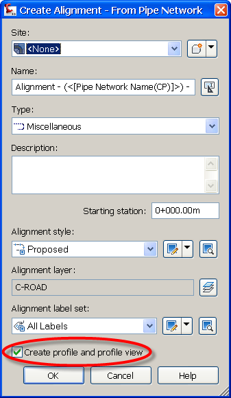
When done the command will ask for an alignment name, description and applied styles which is nothing different then when creating a roadway alignment.
But now you’ll find below an extra option to create a Profile and Profile View directly after you have created the alignment:

Clicking OK will pop-up the Create Profile from Surface dialog:

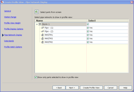
Add all desired surfaces to your profile and click “Draw in profile view”.
Go to Pipe Network Display to check the earlier selected pipes and structures.

Now click “Create Profile View” to create the Profile View in your drawing.

2) Go to your Ribbon, Home tab, Create Design panel and go to Profile and choose the Profile Creation Tools command:

Create a layout profile with the Tangents command by following the bottom of the pipes and/or structures.

3) The next step is to create the Assembly for the Pipe Network (in this case and for simplicity for pipes only). I’ve used a standard TrenchPipe1 assembly with adjusted bottom width and slope settings.

4) Now create a corridor with the Pipe Network Alignment, the newly created profile and the newly created Assembly.
Depending on what you want to calculate choose the right targets for building this corridor. In this case and also to be seen in the uppermost image I’ve used the Exisiting ground as the Target surface.
But as an example find in the image below and to make the picture more visual, slick and clean I’ve used the corridor surface of the road DATUM lines as the Target surface.

Last but not least: Create the corridor surface and use this with your Sample Lines, Sections and Quantities.
There’s nothing different when creating a roadway alignment or an alignment for a pipe network or trench. But Civil 3D has that extra option to create an alignment and profile (View) directly from a pipe network.
Unfortunately a design or layout profile is not or can not dynamically be attached to other objects. If it could then changing your pipe network would result in dynamically update your other corridor and therefor also dynamically update your source data for sections and quantities.
