Archive for March, 2010
Won a price “AutoCAD Tips Competition Winners”
I’ve joined a contest for supplying a tip for AutoCAD. A great initiative of the owner of the blog site (http://cad-notes.com).
Unexpected (to me) I won the 1st price (together with 3 others) which was judged by several (4) international known CAD gurus.
The tip that I’ve submitted can also be read on this blog site: https://c3dpeanuts.wordpress.com/2010/03/02/plotterconfig/
The 1st price includes:
– a batik painting
– a batik shirt/blouse
– an e-book of AutoCAD Block best practices
– an e-book of Revit Architecture
Read more at: http://cad-notes.com/2010/03/autocad-tips-competition-winners/ for more great tips!
Converting Civil 3D objects from Imperial to Metric (and vice versa)
This post is about the conversion of Civil 3D objects from Imperial units to Metric units. Of course this exercise can be reversed to convert from Metric units to Imperial units.
For this exercise I use the LandXML (version 1.2) Import and Export Tool.
Some characteristics of LandXML in short:
Launched January 2000, LandXML.org is committed to providing an non-proprietary data standard (LandXML), driven by an industry consortium of partners.
See for more information: http://www.landxml.org/
The exercise:
- Open the (or a) drawing with Imperial units.
- Go to Toolspace, Settings tab, and select the Active Drawing.
- Right-click on the active drawing and select Edit Drawing Settings.
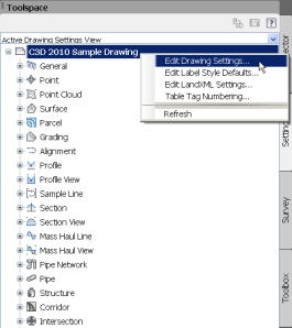
- Check if the Drawing Settings are in Imperial units (Feet).

- Go back to Toolspace, Prospector tab and right-click on the active drawing and select Export to LandXML.
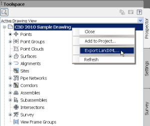
- Choose the latest LandXML version 1.2 and select the Civil 3D objects to export.
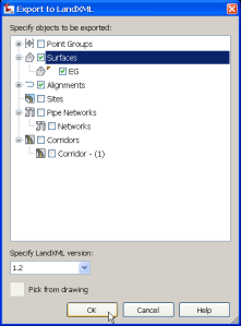
- Choose a apropriate file name and click OK.
- Now open a new drawing (template) with Metric units.
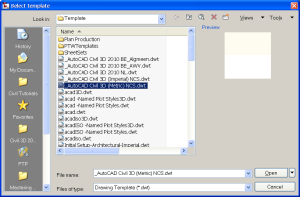
- Check if the Drawing Settings are in Metric units repeating step 2 to 4.
- Go to Ribbon, Insert tab and click LandXML.
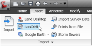
- Select the earlier exported LandXML file and click OK.
- Choose the objects to import, accept or change the import settings and click OK.
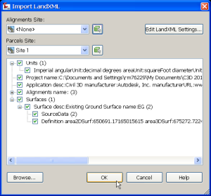
- See the results (the imported objects) in your drawing window and in Toolspace,the Prospector tab.
- Check with the Measure inquiry tools if the objects are converted correctly.
There are a lot of applications right now who have the LandXML import/export supported.
And lots of them are Autodesk based. Take a look at this blog of Jeremy Tammik about the API of Revit and a ‘script’ how to import LandXML data into Revit. The sample program shows a way to import surface data from Civil 3D through LandXML into Revit. See: http://thebuildingcoder.typepad.com/blog/2010/01/import-landxml-surface.html
Another conversion tool is the GENIO Import/Export tool from Autodesk. With this tool you can import from MX Roads objects (features) to Civil 3D objects and vice versa. A short instruction can be found at the Autodesk website, Services & Support, Civil 3D, Documentation, under the Skill Builders. See also: http://usa.autodesk.com/adsk/servlet/index?siteID=123112&id=8777904#section3
Copy and/or Paste Surfaces
I’ve looked for an explanation or instruction of how to Paste Surfaces in AutoCAD Civil 3D.
I have several sources available to me to start with. The following 4 textbooks and 2 eLearning modules about Pasting Surfaces in AutoCAD Civil 3D I’ve read:
The textbooks:
- Digging into AutoCAD Civil 3D 2010 (Rick Ellis)
- AutoCAD Civil 3D 2009 for Engineers (Prof. Sham Tickoo)
- Mastering AutoCAD Civil 3D 2010 (James Wedding/Scott McEachron)
- Learning AutoCAD Civil 3D 2010 (Autodesk)
The eLearning sites:
- eLearning (4D Technologies via AUGI website)
- vBooks (via APW-CTS)
The textbook Digging into AutoCAD Civil 3D 2010 was the only one of the 4 textbooks that gives me an example how to Paste a Surface into another first by copying the Surface with standard AutoCAD commands. Which leads to several cautious steps to take before acting the actual Paste Surface command. This will also lead to that the copied surface doesn’t have any (dynamic) relation with its source surface anymore. So changes made to the source surface will not automatically change the newly created and pasted surface.
The textbook Mastering AutoCAD Civil 3D 2010 was the only one how to Paste a Surface the right way.
Both the eLearning sites give an explanation of Pasting Surfaces but only one gives more meaningful but short explanation on how to use it. The one from 4D Technologies (Wendy Miller speaks) is good enough as an example how to use it right.
So here’s Wendy Miller’s instruction: (For author protected reason’s I make use of other materials).
Case: Say for example you have a Existing Ground Surface (EG) and a Pond Surface (Pond) made of grading feature lines. You want to make a new Finished Ground Surface (FG) with the Pond surface (Pond) pasted into it but leaving the EG surface compleet as it is.
- Create a new Surface from the Toolspace, Prospector and name this surface FG. Use the Suffix “-*” to create this surface on a spearate layer.
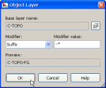
- Go to the Prospector tab and expand the newly created surface FG, go to the Definition part and right-click on Edits, and select Paste Surface
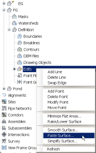
- Select the Existing Ground (EG) Surface, and click OK
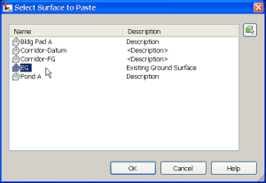
- The newly created Finished Ground (FG) Surface now has the EG surface copied into it.
- Now go again in Prospector to the FG Surface, Definition, Edits, Paste Surface and select the Pond surface,
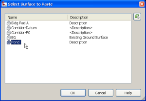 and click OK.
 - Now the Pond surface is pasted into the FG surface.
This way you’ve created the new Finished Ground (FG) surface derived from the Existing Ground (EG) surface and pasted the Pond surface into it.
The FG surface will dynamically update when either the EG surface and/or the Pond surface are changed.
If you want to make individual surfaces which are not linked to one another then you have to make use of the AutoCAD copy command to duplicate the surface and rename it to FG before pasting the pond surface to the copied FG surface. But then again you have to make sure to freeze or thaw all needed layers in this procedure to get a good visual from what you’re doing. And I even don’t have to mention the AutoCAD copy command which could lead to a (say even the smallest) displacement of the copied surface from the source when done wrongly.
This way the FG surface is not dynamically connected to the EG surface but only the Pond surface is dynamically connected to the FG surface.


