Archive for May, 2010
CleanUp installed msi packages
After following the Beta progam of Civil 3D 2011, I’ve decided to replace Mad River with the final release.
Doing an uninstall of the Civil 3D Beta software, for some good reason I had to break off the long uninstall action. And that’s what I shouldn’t have done: I could not intall Civil 3D 2011 anymore.
I followed some Twitter tips pointing me to the BeingCivil Blog site and the Autodesk Knowledge Base, how to succesfully uninstall Civil 3D 2011. Here are the links:
- BeingCivil: http://beingcivil.typepad.com/my_weblog/2010/04/2011-clean-installation-changes.html
- Autodesk: http://support.autodesk.com/getDoc.asp?id=TS14929539
Inspite of the in depth explanation on both web site pages, it didn’t solve my problem.
One other Tweet tip lead me to look at the installation log file. An error: 1638, which tells me that it couldn’t remove an installed msi giving the advice to remove a previous release of the software first via Add/Remove Programs . The log didn’t mention exactly what the name of the msi package was. The only thing I knew was that it rolled back as soon as it tries to install the Civil 3D 2011 Language Pack.
But I couldn’t find this msi package in the Add/Remove Programs.
It was Groundhog Day to me, trying to reinstall the software over and over again, at the end it left me with a rollback action uninstalling the software back to start again.
After several attemps removing the software as clean as possible, I’ve decided to fill in a support request at Autodesk subscription web support.
Waiting for an answer of Autodesk web support I’ve decided to do a last attempt: I’ve tried to Google only for the error 1638, which now resulted in a page where I could download a small but nifty tool: the Windows Installer CleanUp tool.
Running this tool will find all the installed msi packages. And that’s more then Add/Remove Programs does. On the other hand msi packages installed with the main package should only be removed when uninstalling the main package and therefor not need to be listed in Add/Remove Programs. In my case it was the Civil 3D Mad River Language Pack which got corrupted doing my break-off action during an uninstall….
With the Windows Installar CleanUp tool I now could easily remove the ‘hard to removed’ or corrupted msi package.
After this was done, I finally could install Civil 3D 2011 without any problems.
Here’s the link for description and download of the Windows Installer CleanUp tool:
http://support.microsoft.com/kb/290301
Get those Earthwork Volumes of a layout Pipe Network
During one of my training classes doing a pipe networks exercise one of my students asked me how to calculate the earthworks (cut volumes) needed for putting a pipe network into place which is designed next to or attached to a centerline roadway alignment.
In my preparation of this course day I thought it was an advanced topic but also realised it could be done by creating another corridor.
Normally when you design a pipe network you start with an alignment, a profile, an assembly and eventually the corridor. And of course a surface of the existing ground needs to be in place. This is the same process as you would do when doing roadway design.
But in this case you already have the alignment of the roadway and the layout pipe network is attached next to it.
So how do I calculate the earthworks needed for this layout pipe network? Do I use the same alignment?
In fact you need to create another corridor for the pipe network, like you did create a corridor for the roadway.
But now your alignment isn’t the centerline of your roadway but instead the centerline of your pipe network will be used as the alignment.
So after you have placed your pipe network in Plan View and in Profile View, you need to do the following steps before creating the other corridor.
- Create an alignment for your pipes or Pipe network.
- Create a new profile with the bottom of the pipe network as the basis of your profile.
- Create a new assembly for the pipe network.
- Built your other corridor (and corridor surface) based on above items.
These 4 steps will be explained in more detail below:
1) Go to your Ribbon, Home tab, Create Design panel and go to Alignment and choose the Create Alignment from Network Parts command.

The command will ask for the structures and /or pipes to select that will be part of the alignment.
When done the command will ask for an alignment name, description and applied styles which is nothing different then when creating a roadway alignment.
But now you’ll find below an extra option to create a Profile and Profile View directly after you have created the alignment:

Clicking OK will pop-up the Create Profile from Surface dialog:

Add all desired surfaces to your profile and click “Draw in profile view”.
Go to Pipe Network Display to check the earlier selected pipes and structures.

Now click “Create Profile View” to create the Profile View in your drawing.

2) Go to your Ribbon, Home tab, Create Design panel and go to Profile and choose the Profile Creation Tools command:

Create a layout profile with the Tangents command by following the bottom of the pipes and/or structures.

3) The next step is to create the Assembly for the Pipe Network (in this case and for simplicity for pipes only). I’ve used a standard TrenchPipe1 assembly with adjusted bottom width and slope settings.

4) Now create a corridor with the Pipe Network Alignment, the newly created profile and the newly created Assembly.
Depending on what you want to calculate choose the right targets for building this corridor. In this case and also to be seen in the uppermost image I’ve used the Exisiting ground as the Target surface.
But as an example find in the image below and to make the picture more visual, slick and clean I’ve used the corridor surface of the road DATUM lines as the Target surface.

Last but not least: Create the corridor surface and use this with your Sample Lines, Sections and Quantities.
There’s nothing different when creating a roadway alignment or an alignment for a pipe network or trench. But Civil 3D has that extra option to create an alignment and profile (View) directly from a pipe network.
Unfortunately a design or layout profile is not or can not dynamically be attached to other objects. If it could then changing your pipe network would result in dynamically update your other corridor and therefor also dynamically update your source data for sections and quantities.
The new GENIO import/export extension tool for Civil 3D 2011
Very recently the new GENIO import/export extension tool for Civil 3D 2011 is released and it can be downloaded from the Autodesk Subscription website.
The GENIO tool is a conversion tool like LandXML does for exchanging Civil elements but now especially from MX-strings from Bentley’s Civil solution: MX ROADS.
One interesting and new feature is the possibility to import the 3D model of MX ROADS into Civil 3D 2011. This 3D model is saved in the model.fil file and has more possibilities for converting the model into Civil 3D objects then previously released versions.
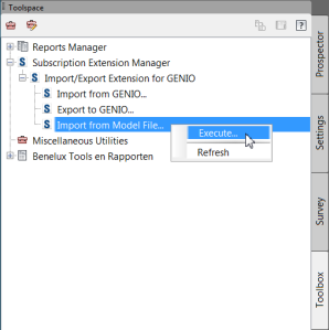
After installing the tool a command will be made available in the Toolspace Toolbox tab under Subscription Extensions. Right clicking and selecting Execute will start the command.

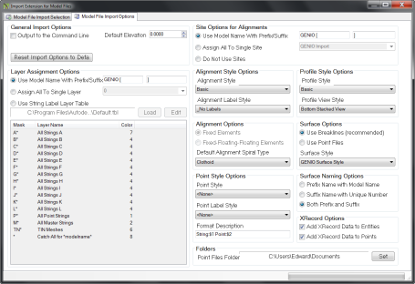
The command has two tabs, where the first one let you choose for the available MX-strings to convert from the model. And where the other tab will let you make settings for the conversions like putting an alignment into a site or not, and assigning styles.

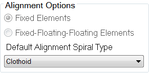
One particullar conversion setting had my attention: Alignment Options settings.
With the option for
– Fixed Elements or
– Fixed-Floating-Floating Elements
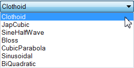
And the option to choose the type of Spiral:
Unfortunately both options for chosing the elements are greyed out and the default value Fixed Elements is selected.
With this default, an alignment converted from MX ROADS always loses it’s tangency if applied between the horizontal alignment elements.
I hope this feature will be implemented in the near future, as the Fixed-Floating-Floating option will possibly remain the tangency.
And this would be a great benefit and advantage because if you need to make some changes to the alignment you always have to go back to the source or you have to reconstruct the alignment in Civil 3D.
At the Autodesk website under Skillbuilders you will find a description how to use the GENIO tool and how to use the data dynamically with data-shortcuts. http://usa.autodesk.com/adsk/servlet/index?siteID=123112&id=7151908&linkID=9240695
Later I will continue explaining other settings in detail.


